
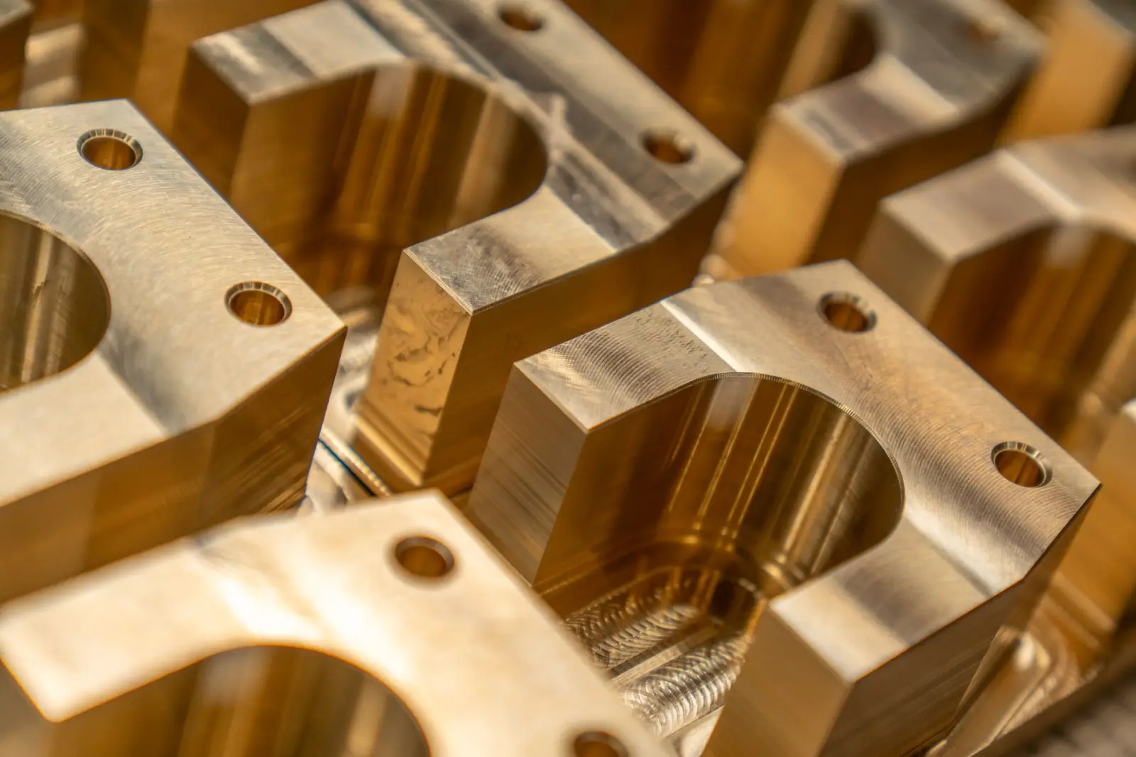
Ra vs Rz is not a question of precision versus convenience — the two parameters look at different things, and a surface can pass on one while failing catastrophically on the other. Two parts can carry the same Ra, come off different machines, and only one of them will seal. If your drawing says "Ra 1.6" and nothing else, you have not specified the surface; you have specified an average.
This matters commercially, not just technically. Surface finish is one of the top reasons machined and cast parts get rejected at incoming inspection, and the argument is almost always about which parameter, measured how, over what length.
Ra vs Rz: What Each One Actually Measures
Ra is the arithmetic mean of the absolute deviations of the profile from its mean line, over the evaluation length. It is an average. Every peak and valley contributes in proportion to its area, so a single deep scratch on an otherwise smooth surface barely moves the number.
Rz is a peak-to-valley parameter: the mean of the largest peak-to-valley heights measured in each of five consecutive sampling lengths. It is dominated by extremes. One deep scratch inside a sampling length changes Rz immediately.
That difference in what they see is the whole story:
| Ra | Rz | |
|---|---|---|
| Type | Average of deviations | Mean of five max peak-to-valley heights |
| Sensitive to | Overall texture | Isolated peaks and valleys |
| Blind to | Single deep scratches, isolated peaks | Fine texture between the extremes |
| Typical use | General texture control, machining consistency | Sealing faces, fatigue-critical surfaces, coating adhesion |
| Reacts to a stray tool mark | Barely | Immediately |
The Same Ra, Two Different Parts
Picture two profiles measured on two shafts, both specified at Ra 1.3 µm.
The first is a uniformly ground surface: consistent, roughly periodic texture, peaks and valleys of similar size. Its Rz lands around 4 µm. The ratio of Rz to Ra is close to 3.
The second is smoother than the first over most of its length, but carries a handful of isolated scratches about 12 µm deep from a chip that got dragged during finishing. Averaged across the evaluation length, those few valleys contribute little — Ra still reads about 1.3 µm. Rz reads around 12 µm, a ratio near 10.
Both parts pass an "Ra 1.3 µm max" drawing note. Put an O-ring on each and only the first one seals: the scratches on the second run straight across the sealing line and give the fluid a path. This is why sealing faces, hydraulic components and fatigue-critical surfaces are specified with Rz — or with both — rather than Ra alone. It is the same class of problem as tolerance stack-up, where every individual part measures in spec and the assembly still fails.
Why There Is No Conversion Factor
You will see Rz ≈ 4 × Ra quoted as a rule of thumb, sometimes Rz ≈ 7 × Ra. Both are observations about particular machining processes, not conversions, and they are exactly the assumption the second shaft above breaks.
The ratio depends on how the surface was made:
| Process character | Typical Rz / Ra ratio |
|---|---|
| Uniform, periodic (fine grinding, honing) | 3–5 |
| Turned or milled with regular feed marks | 4–7 |
| Surfaces with isolated defects, tears or inclusions | 8–15+ |
A conversion table cannot recover information that Ra discarded. If the buyer's drawing calls Rz, measure Rz; converting from your Ra reading and reporting the result is a claim your test report cannot support, and it is the kind of thing that surfaces during a supplier audit rather than during production.
The Cutoff Nobody Specifies
Here is the part that turns a specification argument into a two-week email chain: the same physical surface produces different Ra values depending on the filter cutoff used to measure it.
The measured profile contains both roughness (short wavelength) and waviness (long wavelength). A filter, the profile cutoff λc, separates them. Choose a longer cutoff and more of the waviness counts as roughness, raising Ra. The standard sampling-length rules tie λc to the expected roughness range — 0.8 mm is the common default for the mid range — but "common default" is doing a lot of work in that sentence.
So a complete callout needs, at minimum:
- The parameter — Ra, Rz, or both, each with its own limit
- The limit and its sense — maximum, or a max/min pair
- The cutoff λc and the evaluation length, if not the default for that range
- The lay — the direction of the dominant surface pattern, since roughness is measured perpendicular to the lay and reading along it gives a much lower number
- The surface it applies to — the specific face, not the whole part
Miss any of these and two honest labs can measure the same part and disagree by a factor of two.
What Changed in 2021
In December 2021 the ISO 21920 series formally replaced ISO 4287, ISO 4288, ISO 1302 and parts of ISO 13565 for profile surface texture. If your drawing template still cites ISO 1302 for the finish symbol, it is citing a withdrawn document.
Two practical consequences:
- Ra is now computed once across the whole evaluation length, whereas Rz is still the average of five sampling sections. Under the older definitions the order of operations differed, so a re-measured legacy part can report a slightly different Ra without anything about the part having changed. On profiles containing form error, the difference is not always small.
- The drawing indication changed. Old symbols still appear on legacy drawings and remain readable, but new drawings should follow ISO 21920-1.
There is a parallel system to keep straight: North American drawings often reference ASME B46.1, which defines its own parameter set and historically differed from ISO on how Rz was derived. Legacy German drawings may carry "Rz DIN," which is not identical to ISO Rz either. When a drawing says Rz and does not say under which standard, ask before quoting — the same rule that applies to product dimension tolerance in general.
How to Write a Callout That Gets Accepted
A finish specification that survives incoming inspection reads like this:
Sealing face A: Rz 6.3 µm max, Ra 1.6 µm max, λc 0.8 mm, lay perpendicular to axis, per ISO 21920-1.
Compare that to "Ra 1.6" floating in a general note, and it is obvious which one a buyer's quality department can accept without a phone call.
Surface finish spec checklist
- Parameter named explicitly (Ra, Rz, or both), not just a number
- Standard and edition cited (ISO 21920-1, or ASME B46.1)
- Cutoff λc stated when it is not the default for the range
- Lay direction shown with the correct symbol
- Callout attached to a specific face, not applied part-wide by default
- Different requirements for different faces shown separately
- Measurement direction agreed if the part geometry makes it ambiguous
- N-grade equivalents (N1–N12) translated to µm if a legacy drawing uses them
That "attached to a specific face" line is where most spec sheets fall down. A general note applied to the whole part either over-specifies every surface, which raises your cost, or leaves the critical face ambiguous, which raises your risk. The fix is geometric: the finish callout belongs on a leader pointing at the actual face on the drawing, alongside the dimensions that locate it — which means the drawing has to carry real, measured geometry rather than a decorative illustration. Software that snaps dimensions to the actual edges and lets you place callouts on the feature they govern produces something a quality engineer can act on; a redrawn or generated image produces a picture of a part with numbers floating near it. The same principle applies when you specify powder coating and corrosion requirements, and it is what separates a usable spec sheet from a brochure.
FAQ
What is the difference between Ra and Rz?
Ra is the arithmetic average of the profile's deviations from its mean line, so it describes overall texture and is barely affected by isolated defects. Rz is the mean of the five largest peak-to-valley heights across the evaluation length, so it is dominated by the deepest valleys and highest peaks. Two surfaces with the same Ra can have very different Rz, and the one with the higher Rz is the one that leaks.
How do you convert Rz to Ra?
You do not. The ratio between them depends on the surface's character and ranges from about 3 on a uniformly ground surface to well over 10 on a surface with isolated scratches. Rules of thumb like Rz ≈ 4 × Ra describe specific processes and fail exactly where the distinction matters. If the drawing calls Rz, measure Rz.
Which is better, Ra or Rz?
Neither is better; they answer different questions. Use Ra to control general texture and machining consistency. Use Rz where a single deep valley causes failure — sealing faces, fatigue-loaded surfaces, coating adhesion, bearing surfaces. Critical parts are often specified with both.
Is ISO 1302 still valid for surface finish symbols?
No. The ISO 21920 series replaced ISO 4287, ISO 4288 and ISO 1302 in December 2021, and drawing indication now follows ISO 21920-1. Older drawings using ISO 1302 symbols remain readable and in circulation, but a new drawing citing ISO 1302 is citing a withdrawn standard.
Why do two labs get different Ra values on the same part?
Usually the filter cutoff, the evaluation length, or the measurement direction. Roughness is measured perpendicular to the lay; tracing along the lay reads much lower. A longer cutoff λc lets more waviness count as roughness and raises Ra. Specifying the parameter, the cutoff and the lay on the drawing removes almost all of this disagreement.
Sources & References
- Differences between ISO 4287 and ISO 21920 — parameter definitions and calculation changes
- ISO 21920 roughness — the 2021 replacement of ISO 4287, 4288, 1302 and parts of 13565
- Surface roughness — Ra, Rz and related profile parameters
- ASME B46.1 — Surface Texture (Surface Roughness, Waviness, and Lay)
- What is ASME B46.1 — scope and relationship to the ISO parameter set