Dimensions / Building materials / PVC pipe / Metric PVC-U pipe
Metric PVC-U pressure pipe is named by its real outside diameter in mm and a pressure class: under EN ISO 1452-2 dn 110 is 4.2 mm thick at PN10 and 6.6 mm at PN16, dn 63 3.0 and 4.7 mm (Greek government specification, Wavin). The wall series changes at 110 mm: up to dn 90 the design coefficient is 2.5, so PN10 is SDR 21; from dn 110 it is 2.0, so PN10 is SDR 26 and SDR 21 becomes PN12.5 (Pipelife). PN is the pressure in bar for water at 20 °C over 50 years, and PN = 20 × design stress ÷ (SDR − 1). Lengths are 5 or 6 m, with solvent or rubber-ring sockets. dn 63 is 2.7 mm wider than 2 in pipe (60.3 mm), so inch and metric meet only through adaptors.
| PN10 wall (dn 110) | PN16 wall | Length |
|---|---|---|
| 4.2mmSDR 26 | 6.6mmSDR 17 | 5 or 6m |
Sources: Greek technical specification. Checked October 2026.
Ten 6 m lengths of dn 110 PN10 for a 60 m main at 6 bar and 30 °C, and a wall read off one cut end, are filled in; change the size, class, temperature or wall and see what the table allows.
EN ISO 1452-2 sets the walls, but its own temperature factors are not published free, so the factors here are the AS/NZS 1477 ones Vinidex prints for ISO-sized pipe.
dn 110 PN10 is counted by effective length, the socket left out: 60 m in 6 m lengths takes 10 lengths and 9 joints; you have 10.
Six-metre lengths are counted by effective length, the socket left out, as Vinidex and CECS 41 state them.
dn 110 PN10 is rated 10 bar at 20 °C; at 30 °C the factor is 0.87, so 8.7 bar, enough for your 6 bar.
PN10 water at 30 °C takes the AS/NZS factor 0.87.
EN ISO 1452-2 asks for at least 4.2 mm of wall on dn 110 PN10; your 4.4 mm meets it. At dn 110 that wall is SDR 25, good for 10.4 bar at a design stress of 12.5 MPa.
EN ISO 1452-2 sets 4.2 mm of wall for dn 110 at PN10.
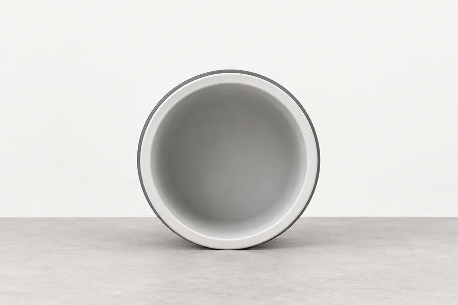
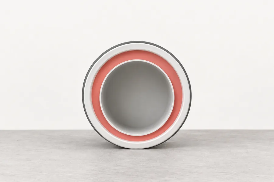
Selling metric PVC-U? Photograph a spigot end with its print line, mark the OD, wall, PN and SDR in SizeMarker, and attach it to the offer.
Mark a photoMinimum wall in mm as the Greek government specification prints the standard; Wavin’s catalogue prints the same.
| dn | PN8 | PN10 | PN12.5 | PN16 |
|---|---|---|---|---|
| dn 20 | — | — | — | 1.5 mm |
| dn 25 | — | — | 1.5 mm | 1.9 mm |
| dn 32 | 1.5 mm | 1.6 mm | 1.9 mm | 2.4 mm |
| dn 40 | 1.6 mm | 1.9 mm | 2.4 mm | 3.0 mm |
| dn 50 | 2.0 mm | 2.4 mm | 3.0 mm | 3.7 mm |
| dn 63 | 2.5 mm | 3.0 mm | 3.8 mm | 4.7 mm |
| dn 75 | 2.9 mm | 3.6 mm | 4.5 mm | 5.6 mm |
| dn 90 | 3.5 mm | 4.3 mm | 5.4 mm | 6.7 mm |
| dn 110This page | 3.4 mm | 4.2 mm | 5.3 mm | 6.6 mm |
| dn 160 | 4.9 mm | 6.2 mm | 7.7 mm | 9.5 mm |
| dn 225 | 6.9 mm | 8.6 mm | 10.8 mm | 13.4 mm |
| dn 315 | 9.7 mm | 12.1 mm | 15.0 mm | 18.7 mm |
Sources: Greek technical specification · Wavin
| Sizes | Design coefficient | PN10 | PN16 |
|---|---|---|---|
| dn 90 and smallerEN ISO 1452-2 | C = 2.5, design stress 10 MPa | SDR 21 | SDR 13.6 |
| dn 110 and largerEN ISO 1452-2 | C = 2.0, design stress 12.5 MPa | SDR 26 | SDR 17 |
| SDR 21 from dn 110Wavin Norway: 160 mm PN12,5 SDR 21 | C = 2.0 | Rated PN12.5 | — |
| GF industrial pipeDIN 8062, EN ISO 15493 | One series at all sizes | SDR 21: 5.3 mm at dn 110 | SDR 13.6: 8.1 mm at dn 110 |
Sources: Greek technical specification · Pipelife · Wavin · GF Piping Systems
| Item | Figure |
|---|---|
| PN from SDRGF planning fundamentals | PN = 20 × σs ÷ (SDR − 1), PN in bar and design stress σs in MPa |
| Design stressGF | σs = MRS ÷ C, MRS 25 MPa for PVC-U, rounded down to the R10 series |
| SDRGF; Pipelife | Outside diameter ÷ wall; SDR = 2 S + 1 |
| What PN meansGF | The highest operating pressure in bar for water at 20 °C over 50 years |
| Solvent insertion depthGF | Half the diameter plus 6 mm: 37.5 mm at dn 63, 61.0 mm at dn 110 |
| Worked at dn 110Our calculation | 4.2 mm wall: SDR 26.2; 20 × 12.5 ÷ 25.2 = 9.9 bar, PN10 |
Sources: GF Piping Systems · Pipelife
EN ISO 1452-2’s own factors are not published free; these are the AS/NZS 1477 factors for ISO-sized PVC-U, with China’s older CECS 41 steps alongside.
| Water | Factor on PN |
|---|---|
| 20 °CVinidex; Holman | 1.00 |
| 25 °C | 0.94 |
| 30 °C | 0.87 |
| 35 °C | 0.78 |
| 40 °C | 0.70 |
| 45 °C | 0.64 |
| 50 °C | 0.58 |
| China, CECS 41:2004 | 1.0 up to 25 °C, 0.8 up to 35 °C, 0.63 up to 45 °C |
| Hottest useGF; Wavin; Vinidex | GF 0–60 °C; Wavin up to 60 °C; Vinidex up to 50 °C |
Sources: Vinidex · Holman · CECS 41:2004 · GF Piping Systems · Wavin
| Item | Figure |
|---|---|
| LengthsGreek specification; Wavin Norway; GF; Vinidex | 5.0 or 6.0 m; 6 m; 5 m plain end; 6 m effective, socket not counted |
| JointsPipelife; Wavin | Solvent-cement sockets or integral rubber-ring sockets; Wavin’s ring-joint range runs 50–400 mm |
| ColourGF; Pipelife; Vinidex | Industrial dark grey RAL 7011; Nordic water main grey-blue, pressure sewer red; Australian Series 1 white |
| StandardsBSI; DIN; SAMR | EN ISO 1452-2:2009 current, revision begun 2026; China’s GB/T 10002.1-2023 replaced the 2006 edition, pressure in MPa (PN1.0 is 10 bar) |
| In the check aboveOur calculation | 60 m ÷ 6 m = 10 lengths and 9 joints; 10 bar × 0.87 = 8.7 bar against 6; wall 4.4 against 4.2 mm, SDR 25, 10.4 bar |
Sources: Greek technical specification · Wavin · GF Piping Systems · Vinidex · Pipelife · Wavin · Pipelife · Vinidex · BSI · DIN · SAMR
Inch outside diameters from Charlotte, converted to mm; the differences are our arithmetic.
| Metric | Nearest inch pipe | Difference |
|---|---|---|
| dn 20 | 1/2 in, 21.3 mm | 1.3 mm smaller |
| dn 32 | 1 in, 33.4 mm | 1.4 mm smaller |
| dn 50 | 1-1/2 in, 48.3 mm | 1.7 mm larger |
| dn 63 | 2 in, 60.3 mm | 2.7 mm larger |
| dn 110This page | 4 in, 114.3 mm | 4.3 mm smaller |
| dn 160 | 6 in, 168.3 mm | 8.3 mm smaller |
| Joining themGF | By adaptors | Very similar, but not identical |
Sources: Charlotte Pipe · GF Piping Systems
Real outside diameters in mm, such as 20, 25, 32, 40, 50, 63, 75, 90, 110, 160, 225 and 315, each in several wall classes: dn 63 is 3.0 mm at PN10 and 4.7 mm at PN16.
4.2 mm at PN10, 6.6 mm at PN16 and 3.4 mm at PN8 under EN ISO 1452-2. Those are SDR 26 and SDR 17, because the design coefficient drops to 2.0 from 110 mm.
The pipe may run at 10 bar with water at 20 °C for 50 years (GF). Warmer water lowers it: × 0.87 at 30 °C and × 0.64 at 45 °C on the AS/NZS factors.
Only up to dn 90. From dn 110, SDR 21 is PN12.5 under EN ISO 1452-2 (Wavin Norway sells 160 mm PN12,5 SDR 21), while GF’s industrial range keeps SDR 21 at PN10.
Only through adaptors: dn 63 is 63 mm against 60.3 mm for 2 in, and dn 110 is 4.3 mm smaller than 4 in, so solvent sockets do not fit across.
GF’s rule is half the diameter plus 6 mm: 37.5 mm at dn 63 and 61.0 mm at dn 110.
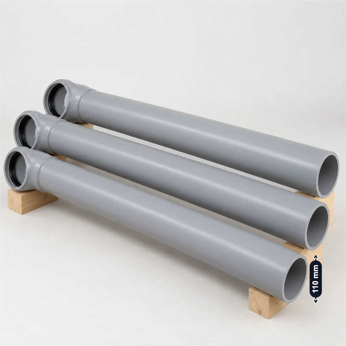
Water-utility and contractor buyers name the dn and PN, but check the SDR and the standard behind it (EN ISO 1452-2, GB/T 10002.1 or DIN 8062), the wall against the table, the effective length, the socket type and ring, the colour and the print line. Mark those on a photo of your own pipe with SizeMarker, the way the picture at the top is labelled, and share one card.