Enter a size and pick a hole class and a shaft class. You get the upper and lower deviations, the limit sizes, and whether the pair runs free, locates or presses. Every value follows the ISO 286 rules and has been checked against published tables.
25 mm falls in the size range over 18 up to 30 mm.
| Largest clearance | 41 µm |
|---|---|
| Smallest clearance | 7 µm |
| H7 upper deviation · largest size | +21 µm · 25.021 mm |
| H7 lower deviation · smallest size | 0 µm · 25.000 mm |
| g6 upper deviation · largest size | −7 µm · 24.993 mm |
| g6 lower deviation · smallest size | −20 µm · 24.980 mm |
Ø25 H7/g6
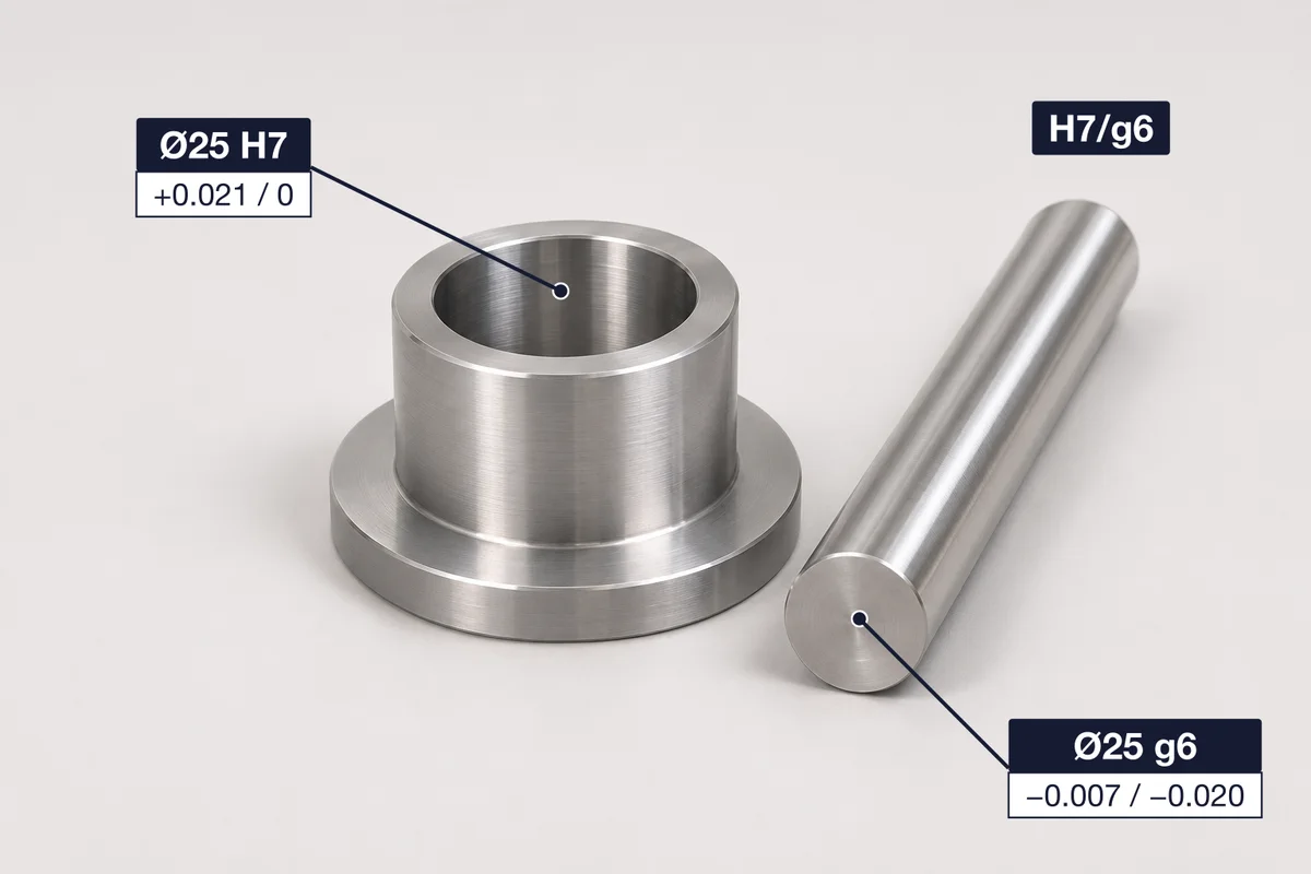
With the limits in mm: Ø25 H7 (+0.021 / 0) and Ø25 g6 (−0.007 / −0.020).
| Clearance fit | +110 … +370 µm | |
| Clearance fit | +65 … +169 µm | |
| Clearance fit | +20 … +74 µm | |
| Clearance fit | +7 … +41 µm | |
| Clearance fit | 0 … +34 µm | |
| Transition fit | −15 … +19 µm | |
| Transition fit | −28 … +6 µm | |
| Interference fit | −35 … −1 µm | |
| Interference fit | −48 … −14 µm | |
| Interference fit | −61 … −27 µm |
Click a row to use that fit.
Deviations are in micrometres (µm); 1 µm = 0.001 mm. Values follow ISO 286-1 and ISO 286-2 and were checked against published ISO 286-2 tables.
Size ranges are “over … up to and including”: a 10 mm part uses the 6–10 mm row, a 10.5 mm part the 10–18 mm row.
Rows with the same values are merged. A dash means the class is not listed in the common tables for that size range.
Mark Ø25 H7/g6 and the limit sizes on a photo of the real part, so the buyer's engineer reads the same numbers your machinist works to.
A fit has two halves: the hole class before the slash and the shaft class after it. Each half is a letter and a number.
ISO 286-1 and ANSI B4.2 recommend a short list of fits so that reamers, gauges and shafts can be standardised. These are the hole-basis ones, from loosest to tightest.
| Fit | Type | Clearance at Ø25 (minus = interference) | Typical use |
|---|---|---|---|
| H11/c11 | Clearance | +110 … +370 µm | Loose running: wide commercial tolerances, parts that see dirt or heat |
| H9/d9 | Clearance | +65 … +169 µm | Free running: large temperature swings, high speeds, where accuracy matters less |
| H8/f7 | Clearance | +20 … +74 µm | Close running: shafts turning in plain bearings on accurate machines |
| H7/g6 | Clearance | +7 … +41 µm | Sliding: parts that move or turn but must locate accurately |
| H7/h6 | Clearance | 0 … +34 µm | Locational clearance: stationary parts that still assemble by hand |
| H7/k6 | Transition | −15 … +19 µm | Locational transition: accurate location, light tap to assemble |
| H7/n6 | Transition | −28 … +6 µm | Locational transition, tighter: more interference allowed |
| H7/p6 | Interference | −35 … −1 µm | Locational interference: rigid, aligned parts pressed together |
| H7/s6 | Interference | −48 … −14 µm | Medium drive: ordinary steel parts, shrink fits on light sections |
| H7/u6 | Interference | −61 … −27 µm | Force fit: highly stressed parts, or shrink fits |
The shaft-basis versions (C11/h11, D9/h9, F8/h7, G7/h6, K7/h6, N7/h6, P7/h6, S7/h6, U7/h6) give similar but not identical results. Pick shaft basis in the calculator to see them.
Upper / lower deviation in micrometres for each ISO size range. Add them to the nominal size for the limits: Ø25 H7 is 25.000 to 25.021 mm.
| Size (mm) | H7 | h6 | g6 | k6 | p6 |
|---|---|---|---|---|---|
| ≤ 3 | +10 / 0 | 0 / −6 | −2 / −8 | +6 / 0 | +12 / +6 |
| 3–6 | +12 / 0 | 0 / −8 | −4 / −12 | +9 / +1 | +20 / +12 |
| 6–10 | +15 / 0 | 0 / −9 | −5 / −14 | +10 / +1 | +24 / +15 |
| 10–18 | +18 / 0 | 0 / −11 | −6 / −17 | +12 / +1 | +29 / +18 |
| 18–30 | +21 / 0 | 0 / −13 | −7 / −20 | +15 / +2 | +35 / +22 |
| 30–50 | +25 / 0 | 0 / −16 | −9 / −25 | +18 / +2 | +42 / +26 |
| 50–80 | +30 / 0 | 0 / −19 | −10 / −29 | +21 / +2 | +51 / +32 |
| 80–120 | +35 / 0 | 0 / −22 | −12 / −34 | +25 / +3 | +59 / +37 |
| 120–180 | +40 / 0 | 0 / −25 | −14 / −39 | +28 / +3 | +68 / +43 |
| 180–250 | +46 / 0 | 0 / −29 | −15 / −44 | +33 / +4 | +79 / +50 |
| 250–315 | +52 / 0 | 0 / −32 | −17 / −49 | +36 / +4 | +88 / +56 |
| 315–400 | +57 / 0 | 0 / −36 | −18 / −54 | +40 / +4 | +98 / +62 |
| 400–500 | +63 / 0 | 0 / −40 | −20 / −60 | +45 / +5 | +108 / +68 |
Ranges are “over … up to and including”. The calculator above covers 67 hole and shaft classes and all 25 size ranges up to 500 mm.
Every limit comes from two numbers in ISO 286-1: the standard tolerance for the grade and size range (Table 1, for example IT7 = 21 µm from 18 to 30 mm) and the fundamental deviation for the letter (Tables 2 to 5, for example g = −7 µm in the same range).
For shafts a to h the fundamental deviation is the upper deviation and the lower one is that minus the tolerance: g6 at 25 mm is −7 / −20 µm. For k to zc it is the lower deviation and the upper one is that plus the tolerance. Holes mirror the shaft values, and from K to ZC a small correction Δ is added for the finer grades, which is why K7 is +6 / −15 µm at 25 mm rather than a simple mirror of k7.
The standard has a few special cases, and the calculator follows them: M6 is −9 µm from 250 to 315 mm, JS7 to JS11 round odd tolerances down so the ± value is a whole micrometre, and N above grade 8 starts at zero for sizes over 3 mm.
We checked the result cell by cell against the Mitsubishi Materials fit tolerance tables (holes and shafts) and the MISUMI tolerance tables, both reproductions of ISO 286-2 / JIS B 0401-2. Where neither table lists a class (s6 above 250 mm, t6 above 180 mm, u6 above 120 mm), the calculator says so instead of showing a number.
+0.021 / 0 mm. The hole may be anywhere from 25.000 to 25.021 mm. Between 18 and 30 mm, H7 is 21 µm wide and starts exactly at the nominal size.
A clearance fit. The smallest hole and the largest shaft are both exactly the nominal size, so the tightest case is zero clearance and the parts can never interfere. At 25 mm the clearance runs from 0 to 34 µm.
In the hole-basis system the hole is H (it starts at the nominal size) and the shaft letter changes the fit. In the shaft-basis system the shaft is h and the hole letter changes. Hole basis is the usual choice because holes are cut with fixed-size reamers and checked with fixed gauges; shaft basis suits drawn bar or standard shafts that many parts slide onto.
The calculator only shows values it can check against a second source. The common ISO 286-2 tables we checked against do not list s6 above 250 mm, t6 above 180 mm or u6 above 120 mm, so those cells show a dash. ISO 286-2 itself goes further; use it for heavy press fits on large parts.
JIS B 0401-1 and -2 (2016) correspond to ISO 286-1 and -2 (2010), and GB/T 1800.1 and 1800.2 (2020) are modified adoptions of the same parts. ANSI B4.2 uses the same metric tolerance classes for its preferred fits. If a drawing cites one of them, the class letters and numbers mean the same thing.