
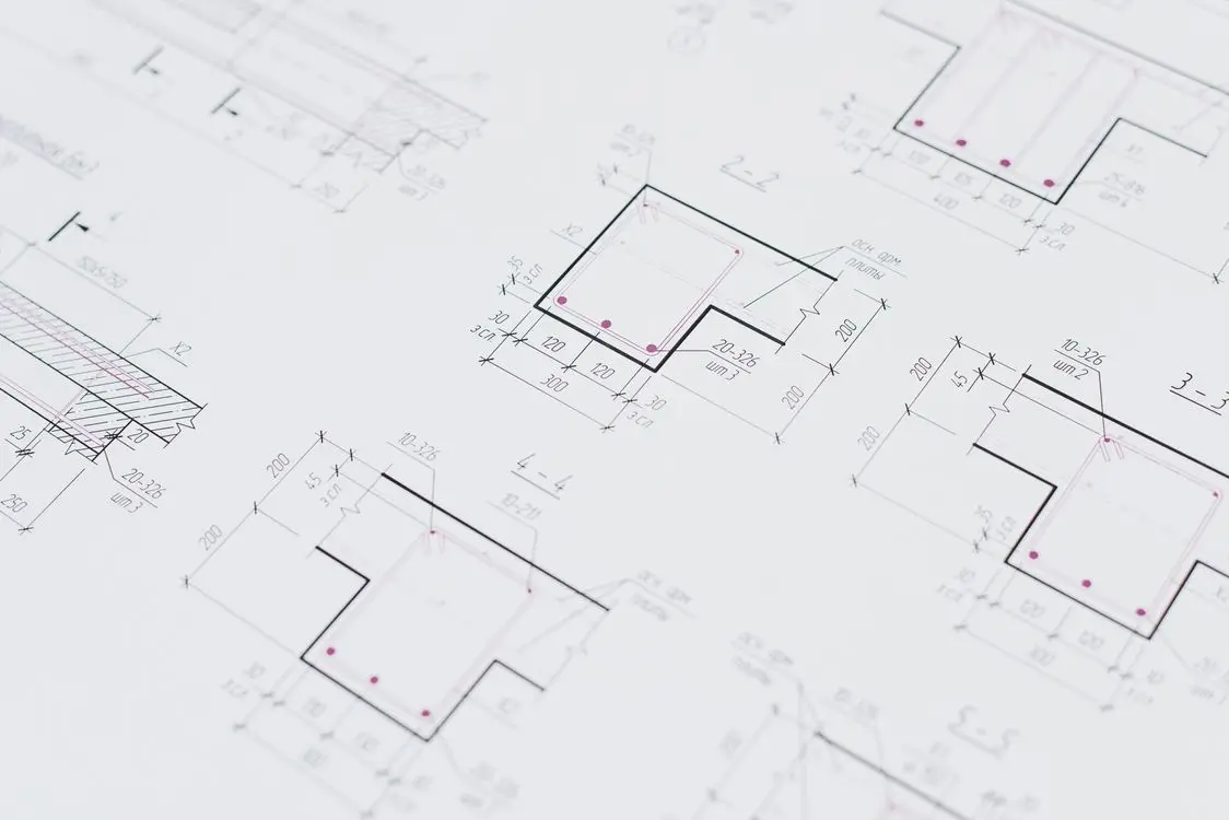
First angle vs third angle projection is not a style preference. It decides which side of the sheet every view lands on, and a drawing read in the wrong convention produces a part that is correct in every dimension and mirrored in exactly one feature — the hole that is 40 mm from the left edge instead of the right. Nobody catches it on the drawing. Everybody catches it at assembly.
The difference is one sentence long: in third angle, each view is placed on the side you looked from; in first angle, it is placed on the opposite side. Everything below is that sentence applied.
First angle vs third angle projection: the whole difference in one table
ISO 5456-2 designates the six views by letter — A is the front view, B the view from above, C from the left, D from the right, E from below, F from the rear — then places them differently depending on the method.
| First angle (formerly "method E") | Third angle (formerly "method A") | |
|---|---|---|
| View B, from above | placed underneath the front view | placed above the front view |
| View E, from below | placed above | placed underneath |
| View C, from the left | placed on the right | placed on the left |
| View D, from the right | placed on the left | placed on the right |
| View F, from the rear | right or left, as convenient | left or right, as convenient |
| Where the object sits | between the observer and the projection planes | behind the projection planes, which are treated as transparent |
| Defining standard | ISO 5456-2:1996, clause 5.1 | ASME Y14.3-2012 (R2018) |
| View conventions built on it | ISO 128-3:2022 (replaced ISO 128-30:2001) | ASME Y14.3 |
| Usual home | Europe, China, India, most of Asia | United States, Canada — and, by convention, Japan |
| Symbol | truncated cone in two views | the mirror image of the first-angle symbol |
Second and fourth angle projection exist geometrically and are used by nobody, which is why the only two arrangements you will ever argue about are the two that put the top view on opposite sides of the same page.
Why the views move: the glass box
Put the object inside a glass box with the faces parallel to its main surfaces, project each face outward onto the glass, then unfold the box flat. That unfolding is the whole mechanism.
In third angle, the projection plane sits between your eye and the object — you are looking through the glass at the object behind it, so the image lands on the near pane and unfolds to the side you were standing on. Look from the right, the right view ends up on the right.
In first angle, the object sits between your eye and the plane — the image is pushed through onto the far pane, and unfolding carries it around to the opposite side. Look from the right, the right view ends up on the left.
That is why one dimension is always shared between adjacent views: width runs across the front and top views, height across the front and side views. When the shared dimension does not line up, you are reading a drawing that was assembled from two conventions.
The 5-second test that works when the symbol is missing
Forget the symbol first. Find the plan.
- Locate the top view — the one that shows the outline you would see from directly above.
- Is it above or below the front view? Above means third angle. Below means first angle. That is the whole test, and it comes straight from the clause: the view from above is placed above in third angle and underneath in first.
- Only two views on the sheet? Now read the title block: the projection symbol lives on or beside it, and many drawings also spell out "FIRST ANGLE" or "THIRD ANGLE" in text. Trust the text over the symbol — a 6 mm symbol does not survive being redrawn at 40 % scale, and the words do.
- Views scattered with letters and arrows? That is a third, legitimate layout — see below — and position tells you nothing at all.
Run those steps before you quote, not after you cut. On a symmetrical part the convention makes no difference and you will never know you got it wrong; on an asymmetric one it is the difference between a shipment and a scrap pile.
The symbol, and why people still misread it
ISO 5456-2 gives each method an identifying graphical symbol — a truncated cone shown in two views — and specifies its proportions. The two symbols are mirror images of each other, and for a good reason: the symbol is nothing more than the placement rule applied to a cone. The frustum's end view sits on the side you looked from in third angle and on the opposite side in first angle, exactly as clauses 5.1 and 5.2 require of any other view.
Which is why memorising "circles on the left means…" is the worst way to carry this around. Under time pressure the mirror flips in your head, and both symbols look like a cone next to some circles at print size. The top-view test in the previous section costs the same five seconds and does not depend on remembering an orientation.
Three things the symbol will not do for you:
- It is not mandatory on a customer's sketch. Standards define the symbol; nothing forces a buyer's procurement team to put one on the PDF they email you.
- It survives copy-paste badly. Rescaled, re-exported, faxed and re-scanned, a 6 mm symbol becomes a smudge.
- It says nothing about units, tolerance defaults or thread standards. A drawing can be unambiguous about projection and still be ambiguous about everything that actually costs money.
The third option nobody uses: reference arrows
ISO 5456-2 clause 5.3 allows a layout most exporters have never been shown. Where strict first- or third-angle placement is inconvenient, the reference arrows method lets views be positioned freely: a lower-case letter in the principal view marks the direction of observation, and the corresponding capital letter is placed above and to the left of each view. The capital letters must always read from the drawing's normal viewing direction.
The clause is explicit that there is no graphical symbol for this method — which is exactly why it confuses people. A drawing with lettered views and no projection symbol is not a defective drawing; it is a different, standard-sanctioned layout, and hunting for a missing symbol on it wastes an afternoon.
Clause 5.4 covers a fourth case worth recognising: mirrored orthographic representation, used in some building and interior work, where the view is a reflection in a mirror placed parallel to the horizontal plane. If a drawing reads as consistently reversed and nothing else explains it, that is the one to check.
Where export orders actually break
First angle vs third angle projection almost never fails at drawing review, because at drawing review everyone is looking at dimensions. It fails two steps later, in the five situations below.
| Symptom | What went wrong | The check that catches it |
|---|---|---|
| Part is dimensionally perfect but mirrored | Drawing read in the wrong convention | Top view above or below? Confirm before quoting |
| Two drawings in one pack disagree | Buyer's US drawing plus your ISO-templated detail sheet | Check the projection note on every sheet, not just sheet 1 |
| Title block says ISO, geometry says third angle | CAD template default never changed after the seat was installed | Compare the symbol against the actual view placement — the geometry wins |
| Views placed with letters, no symbol found | Reference arrows layout under clause 5.3 | Read the letters; stop looking for a symbol |
| Buyer's customer cannot work out the size from your drawing | An engineering drawing was reused as a sales asset | Produce a separate dimensioned image for the listing |
The last row is the one that costs the most and gets discussed the least.
What belongs on a sales drawing, and what does not
An engineering drawing exists to let a machinist reproduce a part. A sales drawing exists to let a buyer decide, in about four seconds, whether the thing fits their space, their pallet or their rack. Those are different documents with different failure modes, and the distinction is worth reading in full in dimension drawing vs spec diagram vs CAD and in spec sheet vs technical drawing.
A practical rule: if your catalogue image needs a projection symbol to be understood, it is the wrong image for a catalogue. Six orthographic views, hidden-detail lines and a title block are an invitation to ask a question, not an answer to one. What converts is a single photograph of the real product with the real measurements locked onto it — overall width, depth, height, plus the two or three clearances buyers actually ask about.
That is a different job from CAD, and the tools are different too. Tools that pin dimensions to a photograph work by measuring the image: you snap a dimension line to the product's actual edge, the geometry is computed rather than guessed, and the annotated file exports at each marketplace's spec-image size. The contrast worth understanding is with AI image generators, which will happily produce a beautiful arrow labelled "60 cm" on a product that is 54 cm wide — a plausible number is not a measured one. See what the finished layout looks like in this dimensioned product image example, and how the same approach is applied across hardware and fittings on the industrial spec diagram page.
Pre-quote checklist
- Top view above or below the front view — write the answer on the quote sheet
- Projection symbol or projection note found on every sheet in the pack
- Symbol and actual view placement agree — if not, ask before cutting
- Units stated (mm or inch) and consistent with the projection convention's usual home
- Lettered views with arrows recognised as clause 5.3, not treated as an error
- Any asymmetric feature — hole, notch, cable exit, hinge side — confirmed against a second view
- Mirrored representation ruled out if the geometry reads consistently reversed
- A separate dimensioned sales image produced for the listing, not a cropped engineering sheet
FAQ
How do I tell if a drawing is first angle or third angle?
Find the top view. If it sits above the front view, the drawing is third angle; if it sits below, it is first angle. ISO 5456-2 states it directly: in first angle the view from above is placed underneath, and in third angle it is placed above. The projection symbol near the title block is the backup check, and an explicit "FIRST ANGLE" or "THIRD ANGLE" note beats both.
Is first angle projection wrong?
No. Both methods are normative. ISO 128-3:2022 — which replaced ISO 128-30:2001 — carries the view conventions, and ISO 5456-2 specifies both methods in detail; ASME Y14.3 governs US practice, where third angle is the working convention. Neither is a downgrade. The only error is not saying which one you used.
Which countries use first angle projection?
As a working generalisation: first angle across Europe and most of Asia, third angle in the United States and Canada. Japan is the trap — Japanese practice is conventionally third angle despite sitting in a first-angle region. Treat all of this as field practice rather than law: nationality does not bind a drawing, the title block does, and a European buyer running US-owned CAD templates will send you third-angle sheets all day.
Do I need a projection symbol on a sales drawing?
No, and you probably should not have one. A projection symbol tells a manufacturer how to read multiple views; a buyer looking at a listing is not reading multiple views. Give the sales asset one photograph, the measured overall dimensions, and the one or two clearances that decide the purchase.
Sources & References
- ISO 5456-2:1996, Technical drawings — Projection methods — Part 2: Orthographic representations (published preview: clauses 4.2, 5.1, 5.2, 5.3 and 5.4)
- ISO 5456-2:1996 — standard catalogue entry and current status
- ISO 128-3:2022, Technical product documentation — General principles of representation — Part 3: Views, sections and cuts, and the earlier parts it replaces
- Swedish Institute for Standards — EN ISO 128-3 scope: views, sections and cuts following the projection methods of ISO 5456-2
- ASME Y14.3-2012 (R2018), Orthographic and Pictorial Views — scope and edition history
- Illinois State Board of Education / CAERT — Differentiate Between First-Angle Projection and Third-Angle Projection: glass box principle, view placement, and why second and fourth angle are unused
- Japanese Standards Association — JIS B 0001, general principles of technical drawing for mechanical engineering